
Structure Composition and Working Principle of Remote-Controlled Lawn Mowers
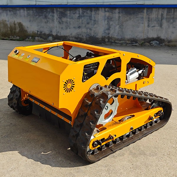
A remote-controlled lawn mower is an integrated garden equipment that incorporates wireless remote control technology, mechanical transmission structures, power supply systems, and intelligent protection systems. Unlike traditional push lawn mowers that rely on manual operation, this equipment enables long-distance unmowed lawn trimming, adapting to weed removal and lawn maintenance on flat turf, steep slopes, orchards, and other complex terrains. The entire machine features a well-defined structural division and coordinated operation among all components. It mainly consists of five core systems: wireless remote control system, power supply system, traveling drive system, cutting operation system, and frame & auxiliary protection system. This article elaborates on the detailed component configuration of each system and comprehensively explains the overall operating mechanism of the equipment.
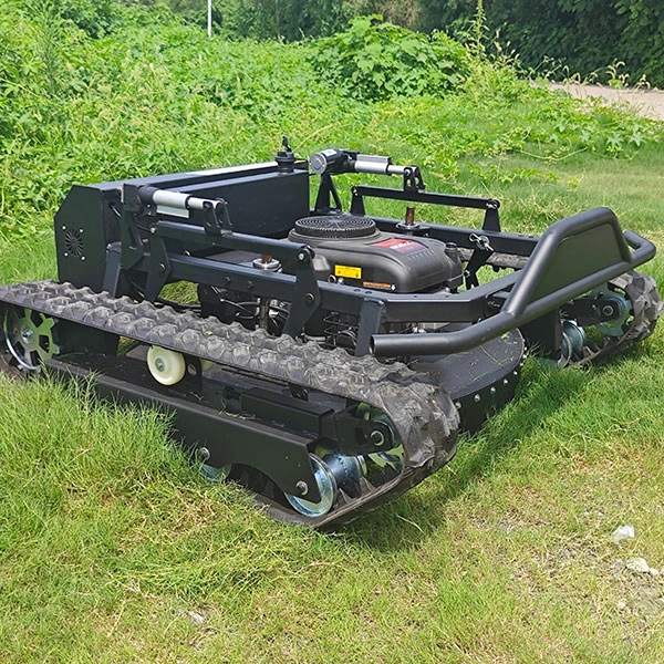
1. Wireless Remote Control System (Core Control Center)
Serving as the brain and nerve system of the remote-controlled lawn mower, this system receives and analyzes manual operation commands, transmits execution instructions, and governs all operational actions of the machine. As the core module supporting remote unmanned operation, it delivers stable signal transmission, strong anti-interference capability, and reliable loss-of-signal protection functions.
1.1 Core Component Configuration
The system is divided into a signal transmitting terminal and a receiving terminal, with fully matched and functional supporting components:
- Handheld Remote Transmitter: The manual operation terminal equipped with a 2.4GHz high-frequency wireless signal transmitting module, control joysticks, multi-function buttons, an emergency stop switch, a battery level display screen, and signal indicator lights. The joysticks precisely adjust the machine’s traveling speed, forward and backward movement, and left and right steering. The functional buttons correspond to starting/stopping the cutting blade, adjusting mowing height, turning on/off the working lights, and other functions. The independent emergency stop button serves as a critical safety component for emergency risk avoidance.
- On-Board Signal Receiver: Installed inside the machine body and paired with the transmitter, it captures wireless radio frequency signals and filters external signal interference to ensure stable and accurate command transmission.
- Main MCU Control Board: The core control chip of the entire machine acts as the command processing hub. It decodes signals from the receiver, converts them into standardized electronic control commands, synchronously coordinates the operation of the power, traveling, and cutting systems, and monitors the real-time operating status of the equipment.
- Signal Protection Components: Including signal loss sensors and automatic power-off relays, these auxiliary parts provide essential safety protection for signal abnormal scenarios.
1.2 Working Principle
Operators input control commands via the handheld transmitter, which sends out wireless radio frequency signals through a dedicated 2.4GHz band. This frequency band effectively resists signal interference from surrounding electrical equipment and terrain obstacles. The on-board receiver captures real-time signals and transmits them to the main control board. After decoding and analyzing the signals, the main control chip converts different commands into corresponding electronic control signals and distributes them to executive components including traveling motors, cutting motors, and height adjustment motors. Meanwhile, the system continuously monitors signal connection status. In case of signal disconnection or over-distance operation, it triggers automatic shutdown and power-off locking immediately to prevent equipment runaway and ensure operational safety.
2. Power Supply System (Core Power Source)
The power supply system provides continuous energy for the machine’s traveling movement, mowing operation, and electronic control system operation. Classified into three types: pure electric, gasoline-powered, and hybrid gasoline-electric, it meets different operational scenarios and endurance requirements, serving as the fundamental guarantee for long-term stable operation.
2.1 Core Component Configuration
- Pure Electric Model Components: High-capacity lithium battery packs (standard 12V 12-20Ah), power voltage stabilization modules, charging protection boards, and battery level detection sensors. Lithium batteries store electrical energy, while the voltage stabilization module ensures stable output voltage and prevents motor burnout caused by overload and voltage fluctuation.
- Gasoline-Powered Model Components: Gasoline engines (5-13.6HP power rating), fuel tanks, fuel line filters, throttle controllers, and cooling fans. As the core power source, the gasoline engine converts fuel combustion energy into mechanical energy. The filter ensures unobstructed fuel delivery, and the cooling components prevent overheating faults during prolonged continuous operation.
- Hybrid Gasoline-Electric Model Components: Integrating gasoline engines and lithium battery packs, equipped with intelligent power switching modules and power generation stabilization devices. Some advanced models are fitted with auxiliary solar charging panels, supporting three flexible working modes: gasoline driving, electric driving, and solar energy supplementary charging.
2.2 Working Principle
For pure electric models, lithium batteries release electric energy, which is regulated by the voltage stabilization module to supply power for all motors, electronic control systems, and sensing devices, featuring stable output, low noise, and zero exhaust emissions. For gasoline-powered models, the engine converts chemical energy from fuel combustion into mechanical energy, which directly drives the traveling and cutting systems, while the built-in power generation unit converts partial mechanical energy into electric energy to power the electronic control system. For hybrid models, the main control system intelligently allocates power output. Gasoline power is activated to provide high torque for heavy-load operations such as slope climbing and large-area mowing, while electric power is adopted for light-duty flat-ground operation to balance power performance and energy efficiency. The solar auxiliary charging module supplements power in real time to extend the machine’s working endurance.
3. Traveling Drive System (Mobility Execution Mechanism)
The traveling drive system controls the overall displacement and posture adjustment of the lawn mower, determining its terrain adaptability, trafficability, and operational flexibility. Current mainstream models are divided into tracked and wheeled structures. Tracked designs deliver superior performance on steep slopes and uneven complex terrains.
3.1 Core Component Configuration
- Power Execution Components: Independently controlled left and right drive motors (650-850W single power rating), reduction gearboxes, and transmission rotating shafts. The dual independent motor design enables unilateral power adjustment and ensures flexible and precise steering performance.
- Load-Bearing Travel Components: Tracked models consist of rubber tracks, drive wheels, guide wheels, load-bearing wheels, and track tensioners; wheeled models adopt four-wheel drive hubs, steering shafts, and anti-slip tires.
- Auxiliary Adjustment Components: Speed sensors and brake relays, used for real-time traveling speed feedback and precise braking control.
3.2 Working Principle
Upon receiving traveling commands from the main control system, the drive motors start operating. The reduction gearboxes reduce motor speed and amplify output torque, driving the drive wheels to rotate through transmission shafts. Tracked models realize steering via the speed difference between the left and right independent motors: synchronous rotation enables straight traveling, while unilateral deceleration or shutdown achieves in-situ steering and fine direction adjustment, adapting to complex terrain operations. Wheeled models complete steering actions through the coordination of steering shafts and motor speed regulation. During operation, speed sensors feed back real-time traveling data, allowing the main control board to dynamically adjust motor speed for stable movement. When stopping, the brake relays lock the motors instantly to prevent sliding and slipping.
4. Cutting Operation System (Core Functional Mechanism)
As the core functional module for lawn trimming and weed crushing, the cutting system directly determines the mowing flatness, operational efficiency, and trimming quality of the equipment. It supports adjustable cutting heights, high-speed cutting, and mulching for lawn soil improvement.
4.1 Core Component Configuration
- Cutting Power Components: High-speed brushless cutting motors, transmission belts, and cutter disc rotating shafts. Brushless motors feature stable operation, low energy consumption, and long service life.
- Cutting Execution Components: Double-sided alloy blades and fully enclosed cutter discs. The alloy blades offer high hardness and wear resistance, while the enclosed cutter discs gather weeds and prevent grass debris splashing.
- Auxiliary Adjustment Components: Electric lifting jacks, height adjustment sensors, and grass crushing guide plates, enabling one-click precise adjustment of mowing height.
4.2 Working Principle
The cutting motor operates at a high speed of 2000-3500 RPM after receiving commands from the main control system, driving the cutter disc and blades to rotate synchronously via the transmission belt. The blades complete 280-350 cutting cycles per minute, efficiently trimming lawn grass and miscellaneous weeds. The electric lifting jacks precisely adjust the ground clearance of the cutter disc, with an adjustable range of 1 to 4 inches to adapt to different grass types and trimming standards. The enclosed cutter disc forms a closed cutting space, which avoids debris splashing and fully crushes weeds for mulching, improving lawn maintenance quality. Height sensors feed back real-time cutter disc height data to ensure consistent trimming flatness across the entire working area.
5. Frame & Auxiliary Protection System (Load-Bearing & Safety Guarantee Mechanism)
This system provides stable load-bearing support for all machine components and integrates multiple protection functions including anti-collision, waterproof, overload prevention, and emergency protection. It is the key to ensuring long-term, stable, and safe operation of the equipment.
5.1 Core Component Configuration
- Load-Bearing Structural Components: High-strength steel frames, integrated equipment housings, and component fixing brackets, which bear all core parts and maintain the overall structural stability of the machine.
- Safety Protection Components: Front and rear anti-collision sensors, waterproof sealing rings, overload protectors, high-temperature alarms, and manual emergency power-off switches.
- Auxiliary Functional Components: Working LED light strips, heat dissipation holes, and shock absorption gaskets, supporting night operation and long-duration continuous work.
5.2 Working Principle
The high-strength steel frame acts as the main load-bearing base, dispersing vibration and working pressure during operation to prevent component loosening and damage. Anti-collision sensors detect obstacles such as walls, trees, and stones in real time, triggering automatic deceleration, steering, or shutdown to avoid collision damage. The waterproof sealing rings form a fully sealed body structure, enabling operation on wet lawns after rainfall and preventing moisture from invading electronic control and power systems. Overload and high-temperature sensors continuously monitor equipment load and operating temperature. Once abnormal conditions such as motor overload or engine overheating occur, the system activates alarms and automatic power-off shutdown immediately, eliminating potential equipment failures and safety hazards comprehensively.
6. Overall Cooperative Working Principle of the Complete Machine
The operation of the remote-controlled lawn mower forms a closed-loop working logic of command input → signal transmission → central processing → power output → mechanical execution → safety monitoring. During operation, the operator sends control commands for traveling, cutting, and height adjustment through the handheld remote transmitter. Wireless signals are transmitted to the on-board main control system, which analyzes and decodes the commands. The main control unit then intelligently dispatches the power supply system to output matched energy, driving the traveling system to complete position movement and the cutting system to perform lawn trimming and weed removal. Throughout the operation process, the protection system and various sensors collect real-time data of equipment temperature, operating load, signal status, and surrounding obstacles, and feed data back to the central control unit. The system dynamically adjusts the machine’s operating state and keeps activating safety protection mechanisms including signal loss protection, overload protection, and anti-collision protection, finally realizing long-distance, automatic, stable, and safe intelligent lawn mowing operation.